Flatpak Permissions on Upgrade, Unravelled
Flatpak has been around for a while, but I’ve not cared about it. I got interested in Fedora Silverblue as a ChromeOS replacement so have been trying Flatpak out on Arch.
It has a sandbox, which is nice, but what is the security model of the sandbox? I can see the permissions before installing a package, but what if those permissions change? Is the sandbox there to restrict the impact of a remote-code-execution of a hacked app, or is it there to protect me against the software packager? Glancing through pages wasn’t clear.
The main difference between the options is, “what happens when an app adds new permissions to its manifest?” If Flatpak happily upgrades it, then the sandbox trusts the software packager. But I didn’t find any documentation about how added permissions are handled.
I followed the org.flatpak.Hello example, building the app and adding it to a repository, then installing the app. I then rebuilt the app to see what the ordinary flow looked like:
$ flatpak update
Looking for updates…


        ID                  Branch   Op   Remote          Download
 1.     org.flatpak.Hello   master   u    tutorial-repo   < 601 bytes

Proceed with these changes to the user installation? [Y/n]:
I then appended to org.flatpak.Hello.yml:
finish-args:
  - --share=network
I rebuilt the app and then updated:
$ flatpak update
Looking for updates…

New org.flatpak.Hello permissions:
    network


        ID                  Branch   Op   Remote          Download
 1.     org.flatpak.Hello   master   u    tutorial-repo   < 647 bytes

Proceed with these changes to the user installation? [Y/n]:
Well, that’s good that it tells me, but it also isn’t the least bit scary and
is easy to miss, especially if there are many updates. I’m also left wondering
what happens with automatic updates. flatpak update --assumeyes is probably a
bad idea (which isn’t mentioned in --help), but --noninteractive looks
promising:
$ flatpak info --show-permissions org.flatpak.Hello
$ flatpak update --noninteractive
Updating app/org.flatpak.Hello/x86_64/master
$ flatpak info --show-permissions org.flatpak.Hello
[Context]
shared=network;
It happily accepts the new permissions without any notification. The output is identical to when permissions stay the same. I had expected it to either error or ignore the update. I’d gladly accept it making an override that denies the new permission, but it doesn’t do that either. I wasn’t really expecting that, because there wasn’t an option to do that interactively.
Now, you could argue “CLI is for advanced usage; use Gnome Software.”
Unfortunately, this hello world example doesn’t show up at all in Gnome
Software, so I couldn’t test. But if I search specifically for gnome software upgrade change permission then I can find Gnome Software issue 943: UX for
Flatpak permission changes on update. It shows Gnome Software is in a
good place, but it doesn’t fill me with confidence about Flatpak overall. If I
had Discover installed and logged into KDE, would I still be okay?
Installs default to system-wide
Using flatpak list I can see apps installed in the “system” Installation.
This is not clear in Gnome Software. Upgrading these apps changes the
permissions for all users, yet I don’t get a “you are about to change your
system” dialog before using elevated privileges. Gnome Software does sorta tell
me if I go to Software Repositories and see “System Installation • 3 apps
installed”.
Apparently it is system-wide because Flathub is configured in
/etc/flatpak/remotes.d/. If the repo is system-wide, then the install is
system-wide. I can accept that logic, but this was done by default by the Arch
flatpak package. The Fedora package
doesn’t include Flathub. Flatpak is aware of this in their setup docs:
Arch vs
Fedora. They encourage the system
installation in their docs, and the flatpak CLI defaults to system
installation.
Easy mistakes with flatpak CLI
I also discovered that flatpak permission-show and flatpak permissions
don’t do what they would appear. They show only some of the permissions; the
extra permissions granted, above those in the app’s manifest. They also
report no warnings/errors if the app name is mispelled. Very easy to be misled.
flatpak override is poor as well, as there does not seem to be a way to list
all overrides; you need to dig into ~/.local/share/flatpak/overrides, which
at least is documented in man flatpak-override.
$ flatpak override --user --unshare=network org.flatpak.Hello
$ flatpak override
error: Permission denied
$ flatpak override --show
$ flatpak override --user
$ flatpak override --user --show
$ flatpak override --show org.flatpak.Hello
$ flatpak override --user --show org.flatpak.Hello
[Context]
shared=!network;
There’s no UIs for those things in Gnome Software. Given how much I’ve heard about the sandbox in Flatpak, I’m disappointed in the cavalier security usability stance.
How can a user accept permissions?
While doing the above I wondered about Flatseal, because it is particularly powerful in a “can attack you” sense. Flatseal lists “No Network Access” in its permissions in Gnome Software, but it also has an entry for “Arbitrary Permissions” with the description “Can acquire arbitrary permissions”. It seems in that case the various green “No $X access” should be removed.
How bad are other cases? If an app has access to “Pictures folder,” it seems
that is probably mostly predictable. But isn’t it trivial to escape the sandbox
with “Session Services” (--socket=session-bus) using systemd-run? How would a
user know that “No Network Access” is meaningless when the service “Can access
D-Bus services on the session bus”?
But also an app might have access to the session bus because of abstract Unix sockets. From the Flatpak Sandbox Permissions Reference:
Giving network access also grants access to all host services listening on abstract Unix sockets (due to how network namespaces work), and these have no permission checks. This unfortunately affects e.g. the X server and the session bus which listens to abstract sockets by default. A secure distribution should disable these and just use regular sockets.
On Arch, lsof -U | grep @ shows dbus-broker and gnome-session available
as abstract sockets.
If an app has write access to the XDG config directory
(--filesystem=xdg-config) it can write configuration for systemd to start a
service on next login. Write access to the home directory can write .bashrc.
Write access to all settings can change which program is executed with my
custom keyboard shortcuts.
Having the sandbox in many of these cases seems useless, because it takes 10 minutes for an attacker to work around it. This isn’t even to the level that “defense in depth” becomes helpful. I think the only benefit of the sandbox for these is when developing an application and incrementally making your application sandbox-ready. But the user should be told there isn’t a sandbox. Even if it is nominally present, it isn’t providing its function.
Gnome Software does give such permissions red and yellow security levels, but the explanations of the permissions undersells their power and then acts like other permissions are still restricted.
Relatively small beans
When opening a file with a Flatpak app in Nautilus and xdg-open, my entire
environment is copied onto the command line and visible through ps. I
understand some OSes allow users to view each other’s environment and that
secrets need to be shared through files or pipes. But this is still surprising.
By poking around with the CLI I noticed that every time I open a file in a portal or with File Roller it adds a new (permanent?) permission for the opening app. But Gnome Software doesn’t have a UI to show me the added permissions. And the permissions are kept even if I uninstall and reinstall the app.
I can clear out all permissions for a specific app using flatpak permission-reset APP_ID or all apps with flatpak permission-reset --all.
Although the permission rows remains, listing each opened file, just with the
app removed. To delete the row I need flatpak permission-remove TABLE ID, but
each row has to be deleted individually.
Takeaways
I started with a very precise concern, didn’t get a clear answer, and now I have additional concerns. Before this investigation I had thought “if an app doesn’t have both network and data access, then that is progress.”
But I don’t think Flatpak is actually communicating the security impact of permissions. And while I now know the full severity of a longer list of risky permissions, what attacks am I not noticing? And do I actually trust Flatpak that a fully-locked-down “all green” app can’t easily escape given so much wasted effort on permissions elsewhere? (I accept that the sandbox can be escaped, but I want to avoid someone knowledgable only needing 10 minutes to break out.)
Fedora (and Silverblue) doesn’t use Flathub by default. That seems like a wise decision. On that system I could use Flatpak without much worry as it is just a different package format for the distro.
Looking through the ~20 apps I’m interested in, all of them show red in Gnome Software except for two yellows: “Calculator” and “Connections,” both of which have network access (Calculator looks up currency exchange rates). Flathub is looking like just another distro but with each user needing to vet most packagers.
Hugo Migration
I converted the site from XSLT to Hugo. If you notice something awry, please let me know. I’m hoping the change makes posting easy enough for me to do it more frequently.
Hugo felt reasonably natural to me. It isn’t that far away in concept from phppen used by the main ersoft.org, except it isn’t using PHP nor MySQL for its backing store. There were some things that needed figuring out, but that was partly because I wanted to match the existing page structure. The only strong oddity was it not having built-in Atom support.
Surprisingly it had trouble computing URLs for attachments to posts. That same
problem was a pain when implementing the XSLT-powered code. I’m happy for
layouts/_markup/, as it allows fixing the problem without shortcode, which
would have made the posts depend on Hugo. Looks like the next Hugo version will
improve the deault and I might be able to remove my custom code.
Youtube Music Playlist Dumping
Via Google Play Music, I have some old Youtube Music playlists. But there does not seem to be a way to export them into a useful form. Takeout lets you export them, but you just get video IDs and a timestamp which is not immediately helpful and for uploaded music prohibitive to make sense of.
Here’s a javascript snippet that can be pasted into the web inspector while viewing a playlist on music.youtube.com, to dump the track metadata. It exports tab-separated values.
// Scroll to bottom of playlist.
// To save results, right click and "Copy Object".
// Double-check the number of results; if entries are missing, you might need to scroll further.
// (Sometimes the number of entries simply doesn't match the playlist's count. May be limited to auto playlists.)
{
const playlistName = document.getElementsByTagName('ytmusic-detail-header-renderer')[0].__data.data.title.runs[0].text;
const playlist = document.getElementsByTagName('ytmusic-playlist-shelf-renderer')[0];
const entries = ["Video Id\tTitle\tArtist\tAlbum"];
function textFromColumnIfPresent(col) {
  return col.musicResponsiveListItemFlexColumnRenderer.text.runs ? col.musicResponsiveListItemFlexColumnRenderer.text.runs[0].text : "";
}
for (const item of playlist.__data.data.contents) {
  const renderer = item.musicResponsiveListItemRenderer;q
  const id = renderer.playlistItemData ? renderer.playlistItemData.videoId : ""; // Track may be unavailable
  const title = textFromColumnIfPresent(renderer.flexColumns[0]);
  const artist = textFromColumnIfPresent(renderer.flexColumns[1]);
  const album = textFromColumnIfPresent(renderer.flexColumns[2]);
  entries.push(id + "\t" + title + "\t" + artist + "\t" + album);
}
console.log("Found " + (entries.length-1) + " tracks");
console.log("Playlist: " + playlistName);
console.log(entries.join('\n'));
}
Vector 4 Technical Information
I recently came into possession of the Vector 4 Technical Information (P/N 7200-0001) by Vector Graphic Inc, and it is a gold mine. The Vector 4 User’s Manual and Vector 4 Programmer’s Guide seemed to have been standard issue so my family had multiple copies (one per computer), and they are already digitized by bitsavers. But the Technical Information seems to be much rarer, and seems to be oriented toward maintenance shops. But that means it has very detailed information including jumpers, clock timing, and schematics, with lots of text explaining it all. I’ve found it to be extremely helpful for working on my Vector 4.
I’ve happily digitized my copy. The schematics at the end are ledger-size pages (17" x 11") which made them difficult to scan, and unfortunately I was only able to scan them at 400 dpi. They are usable, but the originals are easier to read.
Vector 4 Keyboard Adapter
I was working on an MFM decoder for PulseView to help find bugs I introduced in FlashFloppy. That was working pretty well, but I needed some help keeping count of the current track. Using the Counter decoder on STP signal (step pulse) was pretty close to what I needed, but it wasn’t quite good enough. So I read through all the decoders. And I came across UART.
UART. Wait… Earlier when I was investigating emulating a Vector 4 keyboard I knew from past experience the signal looked pretty similar to serial (RS-232), but it wasn’t quite the same so I thought it’d be a pain to figure out how to configure some hardware appropriately. “Bit banging will be so easy!” (And then it wasn’t; but it was fun.) I hadn’t considered whether it might just be a plain UART. A quick look on Wikipedia confirms, it is totally a plain, ordinary UART.
I plug a USB to UART TTL adapter into my computer and attach the UART to the
keyboard port, fire up miniterm.py /dev/ttyUSB0 300 and… it just
works. Dang, that means it is also trivial to use the UART on the Raspberry Pi
or the
UART on Raspberry Pi Pico with Micropython
or a stm32f1 Blue Pill.
In retrospect, it should have been obvious. The Vector 4 User’s Manual even says as much:
Let’s make an adapter
My real goal is to use a modern keyboard with the Vector 4. I can already do that with USB UART and miniterm, but that requires my computer. It’d be easy to use a Raspberry Pi Zero instead, but it is an overkill and would need to boot each power-on. A microcontroller is ideal if it is easy.
There’s two options for reading from a “modern” keyboard: PS/2 and USB. PS/2 has separate data and clock and doesn’t look too bad, although it is 5V. USB requires USB host support, so the Blue Pill wouldn’t work but the Pico would work with USB On-The-Go. And I already have an adapter cable.
Some searching and I find TinyUSB has a keyboard example. And the example outputs to a terminal via a UART! All I need to do is disable some debug printfs and swap to 300 baud, and build for the Raspberry Pi Pico.
tar xf tinyusb-0.11.0.tar.gz
vim hw/bsp/board.h # change CFG_BOARD_UART_BAUDRATE to 300
cd examples/host/cdc_msc_hid
vim src/hid_app.c src/main.c # disable printfs
mkdir build
cmake -DFAMILY=rp2040 -DBOARD=raspberry_pi_pico .. # Seems fine without -DBOARD
make -j
# copy cdc_msc_hid.uf2 to Pico
The logic analyzer confirms it is working, so now I need a physical adapter. I grab a 6P6C mount I happen to have, solder wires directly to it, and attach it to the Pico. The Vector provides 5V, which is perfect for using USB OTG and powering the Pico. (Power+ground on the right. TX on the left, with RX floating because it is 5V.)
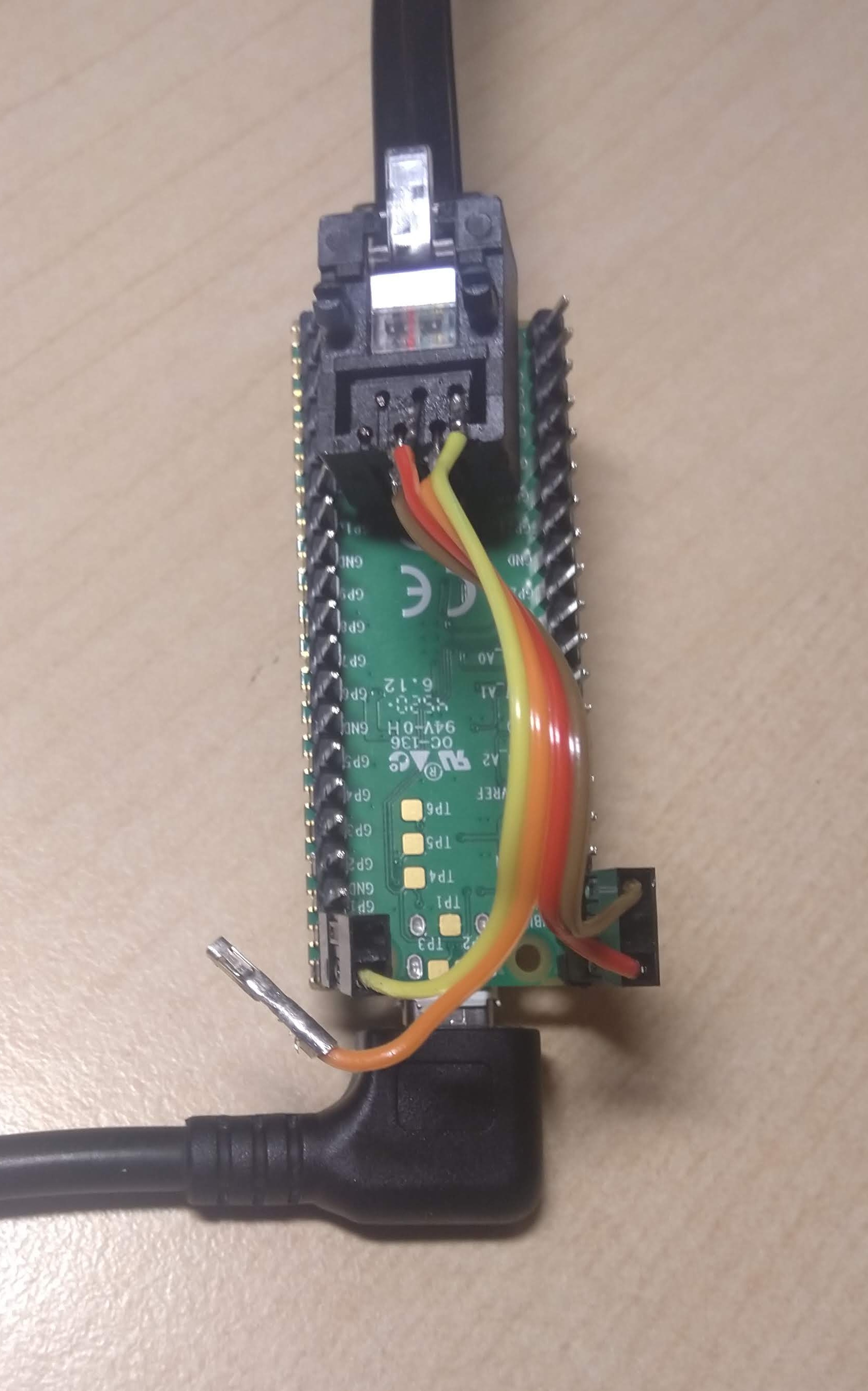
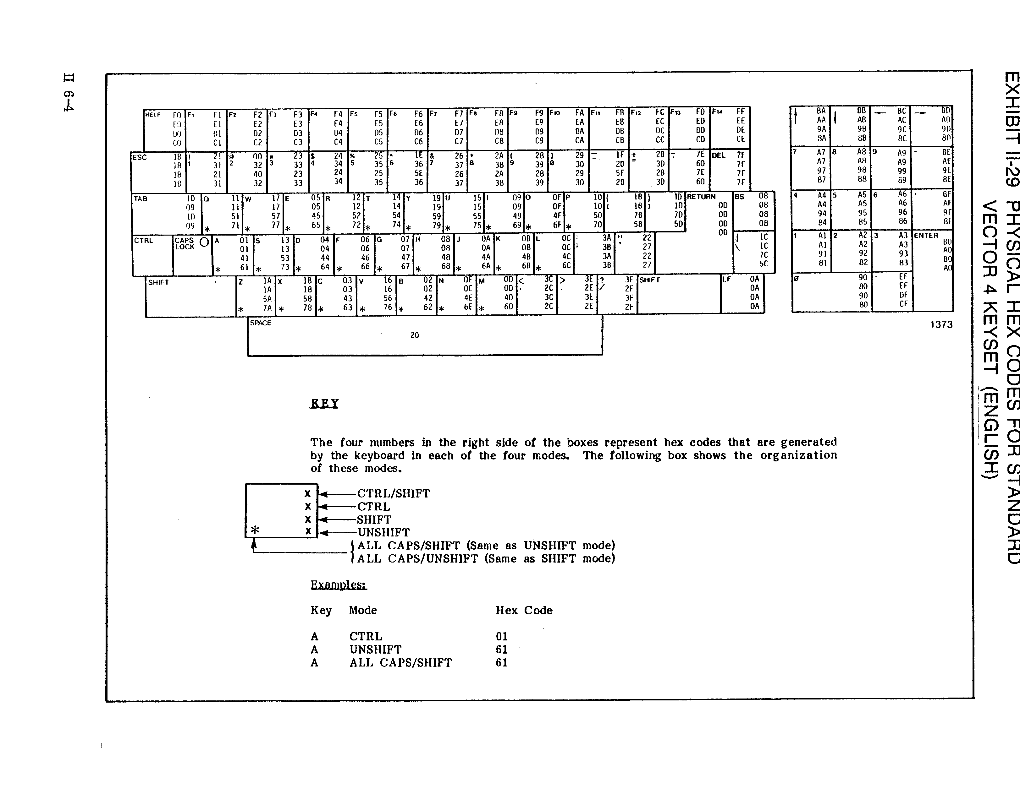
Testing shows it works with the Vector, so then I enhance it to behave more like the original keyboard. Since the last post, I have now obtained the Vector 4 Technical Information (P/N 7200-0001) which provides all the keycodes. I also get rid of the blinking LED and have the LED signal key presses instead. At some point I’ll need to implement auto-repeat when holding down a key, but the patch is already usable.